
 Language
 English
 عربى
عربىIndustry News
The defining distinction among solar cable types is whether they are designed for direct burial in the DC photovoltaic array or for the AC interconnection between the inverter and the utility grid. PV wire (UL 4703) is the only cable type rated for both direct burial and continuous exposure to sunlight in the DC array, with a 90°C wet rating and a 150°C dry rating, making it mandatory for ungrounded transformerless inverter systems operating at 1,000 or 1,500 volts DC. USE-2 cable, while still listed for direct burial, lacks the full sunlight-resistance rating and higher temperature headroom that modern high-voltage arrays demand.
Content
- 1 The four primary solar cable categories
- 2 Comparative specification table for solar cable types
- 3 Voltage class selection and the 1,500 V transition
- 4 Temperature de-rating and ampacity correction
- 5 Insulation chemistry and the XLPE advantage
- 6 Connector compatibility and the MC4 standard
- 7 Grounding and equipment bonding conductor requirements
- 8 Cable management and UV exposure protection
The four primary solar cable categories
A photovoltaic system contains distinct electrical zones, each governed by a specific cable type and a corresponding set of installation requirements under the National Electrical Code (NEC) Article 690. The four cable types that appear in a properly designed system from the array to the point of interconnection are as follows.
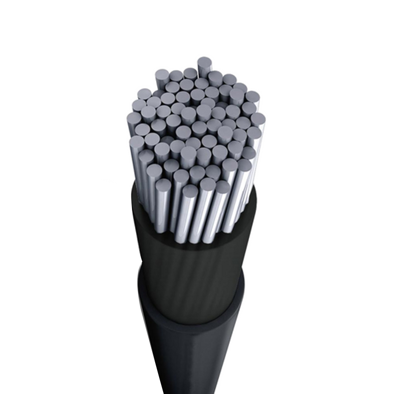
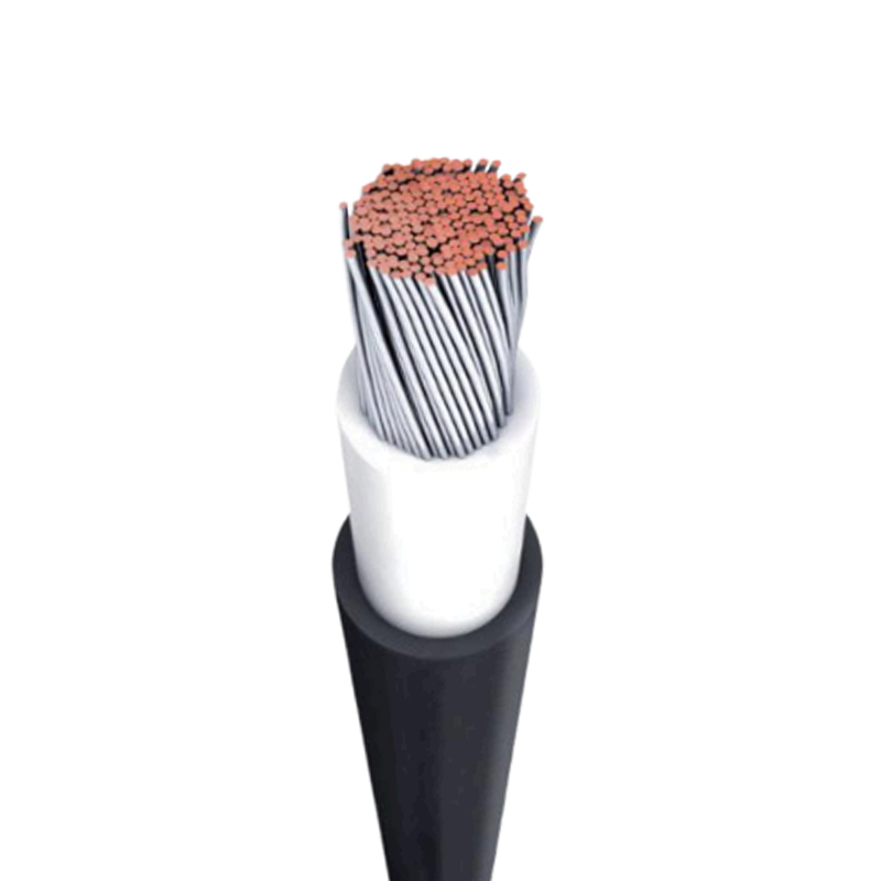
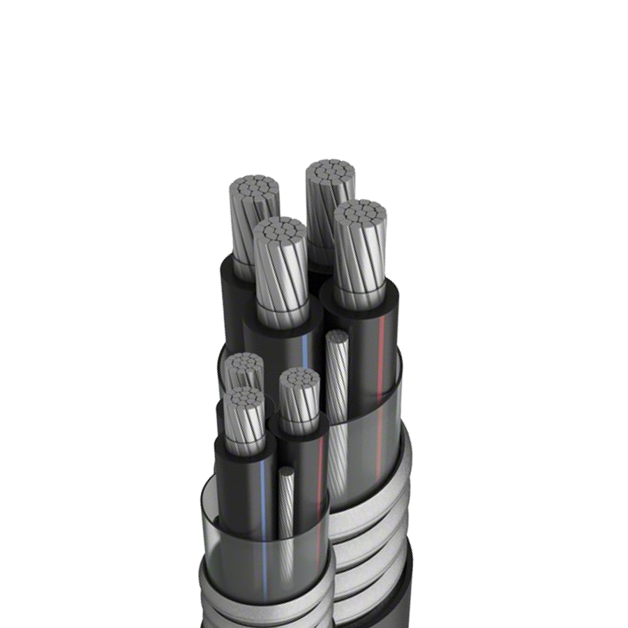
PV wire, listed to UL 4703 and the subject standard UL 4703, is a single-conductor cable with cross-linked polyethylene (XLPE) insulation and a sunlight-resistant outer jacket. It is rated for 600 V, 1,000 V, or 2,000 V depending on the insulation thickness, with the 2,000 V variant specified for 1,500 VDC utility-scale arrays. The XLPE insulation provides thermoset stability, meaning the cable maintains its dielectric strength and mechanical properties even after prolonged exposure to the conductor's maximum operating temperature of 90°C wet and 150°C dry. The tinned copper conductor, stranded according to ASTM B174 Class B or C, resists the corrosive effects of moisture that permeates the insulation over decades of service. PV wire is the only cable in the solar industry that carries a VW-1 flame rating and a direct burial rating simultaneously, satisfying both the fire safety requirement in rooftop installations and the underground routing requirement in ground-mount DC collection systems.
USE-2 cable, built to UL 854 and recognized by NEC Article 338, is a single-conductor cable rated for underground service entrance. It uses XLPE insulation identical in chemistry to PV wire but applies a thicker, more robust jacket designed to withstand the mechanical abrasion of pulling through underground conduit and direct earth contact. Its voltage rating is limited to 600 V, and its maximum conductor temperature is 90°C wet and 90°C dry, a critical limitation compared to PV wire. The absence of a 150°C dry rating means USE-2 cannot be used in free air within a rooftop array where module backsheet temperatures routinely reach 75°C to 85°C and the conductor temperature rise under full load pushes the insulation into thermal overload territory.
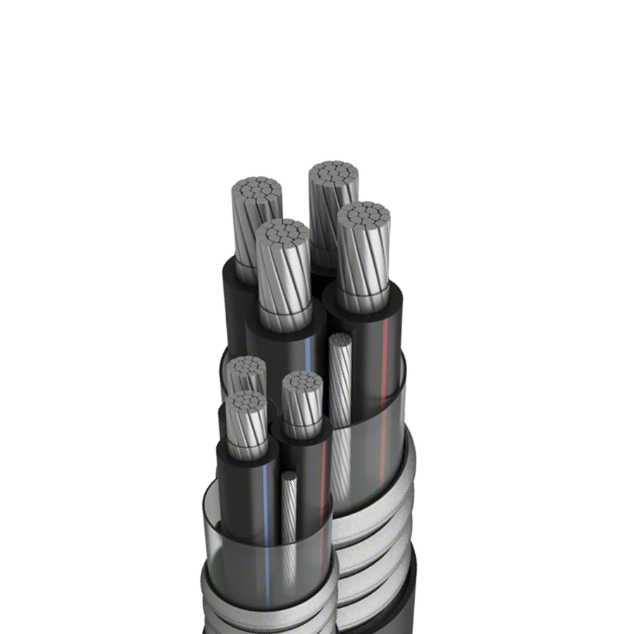
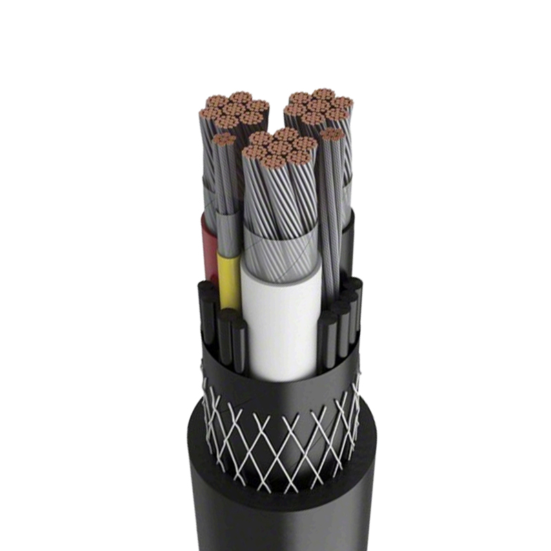
TC-ER cable, tray cable exposed run rated, serves as the DC collection trunk between the combiner box and the inverter input, or between multiple string inverters in a daisy-chain configuration. TC-ER is a multi-conductor assembly, typically three conductors plus ground, with a PVC inner insulation and a nylon or PVC outer jacket. It is rated for 600 V and 90°C dry, and its listing permits routing in cable tray without conduit for the exposed run. The multi-conductor construction simplifies wiring compared to pulling individual single-conductor cables, but the PVC jacket degrades under ultraviolet radiation, so TC-ER must be enclosed when installed outdoors in direct sunlight.
THHN/THWN-2 building wire, while not a dedicated solar cable, appears on the AC side of the inverter output through to the main service panel or utility interconnection point. Rated 600 V and 90°C dry, 75°C wet, with a nylon jacket over PVC insulation, it is cost-effective, widely available, and code-compliant for all indoor AC wiring downstream of the inverter. Its sunlight resistance is zero, and it has no direct burial listing, so its use is strictly confined to interior raceways, conduits, and enclosed AC combiner panels.
Comparative specification table for solar cable types
| Cable Type | Applicable Standard | Max Voltage (VDC) | Wet/Dry Rating (°C) | Sunlight Resistant | Direct Burial |
|---|---|---|---|---|---|
| PV Wire | UL 4703 | 600, 1000, 2000 | 90 / 150 | Yes | Yes |
| USE-2 | UL 854 | 600 | 90 / 90 | No | Yes |
| TC-ER | UL 1277 | 600 | 75 / 90 | No | No |
| THHN/THWN-2 | UL 83 | 600 | 75 / 90 | No | No |
Voltage class selection and the 1,500 V transition
The shift from 1,000 VDC to 1,500 VDC system architectures in utility-scale photovoltaic plants reduces DC collection current by approximately one-third for the same power throughput, cutting the number of combiner boxes, DC feeders, and associated trenching by a similar proportion. However, the higher voltage imposes stricter insulation requirements. A 1,500 VDC array demands PV wire rated for 2,000 VDC, not 1,000 VDC. The insulation thickness on a 2,000 V PV wire is approximately 2.4 mm for 10 AWG conductors, compared to 1.14 mm for the 1,000 V variant. This increased wall thickness reduces the cable's flexibility and increases the minimum bend radius, a factor that complicates wire management within module junction boxes and inverter DC enclosures.
The IEC 62930 standard, applied globally outside North America, harmonizes the performance requirements for 1,500 V PV cables. It specifies a minimum insulation resistance of 10 MΩ·km at 20°C, a figure verified during factory production testing on every reel before shipment. Field testing of installed 1,500 V PV wire with a 5,000 V megohmmeter must yield insulation resistance values not less than 4 MΩ per string before the string is connected to the inverter, a commissioning gate that identifies installation damage to the jacket or improperly crimped MC4 connector seals.
Temperature de-rating and ampacity correction
The ampacity tables in NEC Article 310.15 assume an ambient temperature of 30°C and no more than three current-carrying conductors in a raceway. A solar DC collection system routinely violates both assumptions. On a rooftop in Phoenix, Arizona, where the ambient air temperature 12 inches above the roof surface reaches 65°C on a summer afternoon, the temperature correction factor for 90°C-rated PV wire is 0.58 according to NEC Table 310.15(B)(1)(1). A 10 AWG PV wire with a 30°C ampacity of 40 amps is thus de-rated to 23.2 amps at 65°C. If that same wire is bundled with three other current-carrying strings in a conduit for a distance exceeding 24 inches, an additional adjustment factor of 0.80 applies, further reducing the allowable ampacity to 18.6 amps.
The result is that a 10 AWG conductor, which appears generously oversized for a 9-amp string current at first glance, is operating at nearly 50% of its de-rated capacity after temperature and bundling corrections. Engineering practice for rooftop systems specifies 10 AWG as the minimum PV wire size for module interconnections, with 8 AWG required for home-run conductors serving more than two strings, a rule of thumb derived from worst-case rooftop temperature data rather than a fixed standard.
Insulation chemistry and the XLPE advantage
The insulation material differentiates a solar cable from general-purpose building wire more than any other attribute. XLPE, the cross-linked polyethylene used in PV wire and USE-2, is a thermoset material, meaning the polymer chains are chemically cross-linked during the curing process. Once cross-linked, the material cannot melt or flow when heated. A PV wire exposed to a conductor temperature of 150°C maintains its physical shape and dielectric strength, whereas a PVC-insulated THHN wire at the same temperature would soften, flow, and create an internal short circuit.
The cross-linking process, achieved by a silane-based moisture cure or electron beam irradiation, also improves the insulation's resistance to cold flow under compression. When a PV wire is pinched between the module frame and the mounting rail, the XLPE insulation resists the compressive set that would thin the PVC insulation wall over time. The retained wall thickness after 1,000 hours of compressive loading at 90°C is typically 85% to 90% of the original thickness for XLPE, compared to 60% or less for PVC. This property is essential in a photovoltaic array where module clamps and wire clips apply localized pressure points that persist for the 25-year design life of the system.
Connector compatibility and the MC4 standard
The solar cable itself is only the conductor; the connector termination is the system-level failure point. The industry standard is the MC4 connector, originally developed by Multi-Contact and now manufactured under license by over a dozen global suppliers. The MC4 is rated for 1,500 VDC and 30 amps continuous current with 4 mm² or 6 mm² (12 AWG to 10 AWG) PV wire, and it maintains an ingress protection rating of IP68 when mated, meaning it withstands continuous submersion in 1 meter of water.
The critical rule for reliability is connector-homogeneity: the male and female connectors on a single string must be from the same manufacturer. Mating an Amphenol H4 connector with a genuine Staubli MC4, despite their physical compatibility and UL listing, introduces a galvanic corrosion risk at the contact interface because the base metals and plating thicknesses differ. The resulting contact resistance, measured by a four-wire milliohm meter, may start at an acceptable 0.5 milliohms but can rise to 5 milliohms or more within three years of thermal cycling, at which point the I²R heating at the connector exceeds the surrounding cable temperature and accelerates oxidation. Field failures traced to mismatched connectors are the single most common insurance claim on residential rooftop systems.
Grounding and equipment bonding conductor requirements
The equipment grounding conductor (EGC) in a solar array serves as the fault current return path and must be sized to carry the full short-circuit current of the array without exceeding its rated temperature. NEC Table 250.122 governs EGC sizing based on the overcurrent protection device rating, but for transformerless inverters where DC ground-fault detection is integrated, an EGC no smaller than the largest DC circuit conductor is recommended by engineering best practice, even when a smaller size is permitted by code. A 10 AWG PV wire used as the ungrounded DC positive conductor must be accompanied by a minimum 10 AWG EGC, sized per 690.45 of the NEC.
For the AC side, the EGC between the inverter and the main service panel is typically a THHN/THWN-2 conductor with green insulation, sized per Table 250.122 based on the inverter's AC output overcurrent protection rating. A 40-amp inverter output breaker requires a minimum 10 AWG copper EGC. The EGC is not a current-carrying conductor in normal operation but must be capable of conducting the full ground-fault current for the time required for the overcurrent device to clear the fault, a duration typically less than 0.1 seconds for modern current-limiting circuit breakers.
Cable management and UV exposure protection
Even sunlight-resistant PV wire requires physical protection against sharp edges, wildlife damage, and concentrated UV degradation at stress points. Cables on a ground-mount array are routed through metallic or high-density polyethylene (HDPE) cable tray, secured with stainless steel cable ties at intervals not exceeding 1.5 meters. The cable ties must not over-compress the insulation; a tie tension exceeding the manufacturer's specification can cold-flow the XLPE insulation and reduce the wall thickness at the tie point by 50% within a single thermal cycle.
In rooftop installations, PV wire must be supported off the roof surface by cable clips or module frame-integrated wire management channels. Direct contact between the cable jacket and asphalt shingles transfers heat from the roof surface to the cable, elevating the conductor temperature by an estimated 5°C to 10°C above the ambient air temperature, a margin that can push the conductor temperature beyond its 90°C wet rating when combined with full load current and high module backsheet radiation. The cable must also be routed to avoid standing water in the low points of the roof, where freeze-thaw cycles stress the jacket through repeated expansion and contraction of ice formations.