
 Language
 English
 عربى
عربىIndustry News
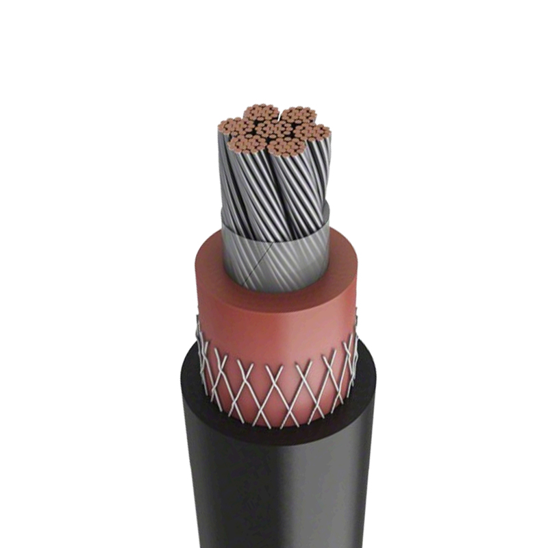
The operational reliability of modern medium and high-voltage networks depends heavily on the dielectric performance of XLPE insulated power cables. Cross-linked polyethylene insulation permits a continuous conductor operating temperature of 90°C, a critical threshold that enables higher current carrying capacity compared to older PVC or paper-insulated cables. For engineers and installers, understanding the precise voltage ratings, permissible bending radii, and testing protocols of XLPE insulated power cables determines whether a circuit will function without partial discharge for thirty years or fail prematurely at a termination.
Content
Voltage Ratings and Insulation Levels
XLPE insulated power cables are manufactured to defined voltage classes that specify the phase-to-phase and phase-to-ground withstand capabilities. The most common medium-voltage designations under IEC 60502-2 are 6/10 kV, 8.7/15 kV, 12/20 kV, and 18/30 kV, where the first figure represents the rated phase-to-ground voltage and the second the rated phase-to-phase voltage. A cable designated 8.7/15 kV must withstand a power-frequency test voltage of 30.5 kV for five minutes during factory acceptance testing, verifying the integrity of the extruded insulation layer.
Selecting the correct voltage rating requires matching the cable to the system's maximum continuous operating voltage and its expected ground fault duration. For a 12 kV system where ground faults are cleared within one second, a 6/10 kV cable may be undersized once transient overvoltages are considered. The insulation thickness scales with voltage class: a typical 15 kV XLPE insulated power cable features 4.5 mm of XLPE insulation, while a 35 kV cable increases this to approximately 8.4 mm. This additional thickness directly affects the cable's overall diameter, bending stiffness, and the pulling tension calculations required during installation.
Current Carrying Capacity and Derating Factors
The ampacity of XLPE insulated power cables is not a single fixed number. It shifts based on installation method, ambient temperature, soil thermal resistivity, and the proximity of neighboring circuits. A 3-core 240 mm² copper XLPE cable rated for direct burial might carry 480 A at 90°C conductor temperature in isolation, but this figure drops significantly when the cable is installed in a duct bank with four other loaded circuits and a soil thermal resistivity of 1.2 K·m/W rather than the assumed 1.0 K·m/W.
The table below presents the typical derating factors applied to XLPE insulated power cables installed in various configurations, based on IEC 60364-5-52 guidelines.
| Installation Condition | Derating Factor | Effective Ampacity (from 480 A base) |
|---|---|---|
| Single cable, free air, 30°C ambient | 1.0 | 480 A |
| Three circuits in trefoil, touching | 0.79 | 379 A |
| Duct bank, 4 circuits, RHO 1.5 K·m/W | 0.65 | 312 A |
| Ground temperature 40°C (vs 20°C base) | 0.87 | 418 A |
The cumulative effect of multiple derating factors is multiplicative. A cable in a four-circuit duct bank with elevated ground temperature might see its effective ampacity reduced to 270 A or less, barely half its free-air rating. Thermal backfill materials with low resistivity, such as cement-bound sand or specifically engineered grouts surrounding the duct bank, become essential mitigation measures to recover lost capacity without upsizing the conductor cross-section.
Installation Tolerances and Pulling Limits
Field installation of XLPE insulated power cables demands strict adherence to minimum bending radii and maximum pulling tensions. The minimum bending radius for a single-core XLPE cable during installation is typically 15 times the cable's overall diameter, increasing to 12 times for three-core cables. Exceeding this radius causes irreversible damage to the XLPE insulation structure: the inner radius compresses while the outer radius stretches, potentially creating micro-voids that evolve into partial discharge sites under operating voltage.
Pulling tension limits protect the conductor and the insulation from mechanical damage during cable laying. The maximum pulling tension for a copper-conductor XLPE cable should not exceed 50 N per square millimeter of conductor cross-section. For a 300 mm² copper conductor, this translates to 15,000 N of allowable pulling force. This tension must be calculated along the entire planned pulling path, including the increased friction at each conduit bend. Cable lubricants compatible with the XLPE jacket material, typically a bentonite or polymer-based gel, reduce the coefficient of friction to approximately 0.25 to 0.35, substantially lowering the required pulling force. The sidewall pressure where the cable bears against the inside of a conduit bend must also be checked, with a typical limit of 1,500 N per meter of bend radius for XLPE cables to prevent insulation deformation.
Termination and Jointing Practices
The points where XLPE insulated power cables connect to switchgear or splice to other cable sections represent the highest statistical failure locations in any network. A properly executed termination reconstructs the electrical stress control that the factory-applied insulation screen provided. The screen cut-back point creates a region of high electrical stress, and a stress control tube or geometric stress cone must grade this potential smoothly from the conductor voltage to ground potential along the termination length.
Heat-shrink terminations for 15 kV XLPE cables require methodical preparation: the outer jacket is removed to expose the metallic shield, the shield is cut to the specified dimension, the insulation screen is peeled back to expose clean XLPE, and the insulation surface is sanded smooth with abrasive grit specified by the termination manufacturer. Any score mark left on the XLPE surface from a careless knife cut during screen removal becomes a partial discharge initiation point. The stress control mastic or tubing must overlap the screen edge by the manufacturer-specified distance, typically 15 mm to 25 mm, to ensure the electrical field lines refract smoothly without surface tracking. After installation, the termination lug must be crimped with a hexagonal die matched to the conductor class and cross-section, applying sufficient compression to achieve a gas-tight cold weld between the lug barrel and the copper strands.
Field Testing and Commissioning
Testing XLPE insulated power cables after installation but before energization is the final gate that catches workmanship defects, transport damage, and termination errors. The accepted commissioning test for new medium-voltage XLPE circuits is a very low frequency sinusoidal waveform at 0.1 Hz, applied for a duration of 30 to 60 minutes. For a 15 kV cable with an 8.7 kV phase-to-ground rating, the VLF test voltage is typically set to 2.0 to 3.0 U₀, corresponding to approximately 18 kV to 26 kV peak.
DC high-potential testing, once standard practice, has been abandoned for XLPE insulated power cables because it deposits space charge in the insulation that can precipitate an in-service failure after the cable is reconnected to AC. The VLF test, combined with tan delta measurement at multiple voltage steps, provides a diagnostic baseline. A new, healthy XLPE cable should exhibit a tan delta value below 0.2 × 10⁻³ with minimal variation between voltage steps. Any cable showing a tan delta exceeding this threshold, or a step-change increase between successive voltage levels, indicates contamination, moisture ingress, or extrusion defects that warrant investigation and potential cable replacement before the circuit is placed into service.
Long-Term Aging and Condition Monitoring
XLPE insulation degrades through two primary mechanisms: thermal aging from sustained operation at or near the 90°C limit, and water tree growth in the presence of moisture and electrical stress. Modern XLPE compounds incorporate water-tree-retardant additives, but cables manufactured before the widespread adoption of these formulations in the 1990s remain vulnerable. Condition monitoring programs use partial discharge mapping and dielectric spectroscopy to identify aging XLPE insulated power cables before they fail in service.
Partial discharge measurement, performed with capacitive couplers at terminations or high-frequency current transformers around the cable earth connection, detects discharges with apparent charge magnitudes as low as 5 to 10 picocoulombs. A cable exhibiting partial discharge inception voltage below 1.3 times the operating voltage is approaching a condition where a fault is probable within the next one to three years. For critical circuits, online partial discharge monitoring systems permanently installed at switchgear terminations provide continuous surveillance of the XLPE insulated power cable condition, triggering alarms when discharge activity changes in magnitude or repetition rate. This data allows asset managers to schedule planned outages for cable replacement rather than responding to an emergency fault that interrupts production or service delivery.