
 Language
 English
 عربى
عربىIndustry News
Content
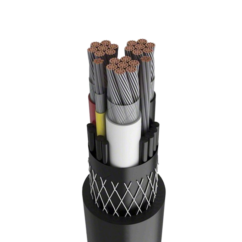
Core Construction and Material Synergy
The deployment of modern electrical infrastructure demands conductors that balance electrical efficiency with mechanical durability. Among the most widely adopted solutions for medium and low voltage distribution networks are XLPE Insulated PVC Sheathed Power Cables. These assemblies integrate advanced polymer chemistry with rigorous manufacturing standards to deliver consistent performance across diverse operating conditions. The structural architecture relies on a multi-layered approach where each component serves a distinct electrical or mechanical purpose. Engineers select these cables because they mitigate common failure modes associated with traditional insulation materials while maintaining cost-effective production methodologies. The synergy between the conductor, insulation layer, and outer protective barrier ensures optimal current carrying capacity without compromising system safety.
Cross-Linked Polyethylene Insulation Dynamics
Cross-linked polyethylene represents a significant advancement over standard thermoplastic materials by undergoing a molecular transformation that creates a three-dimensional network structure. This chemical cross-linking process enhances thermal stability, allowing the material to maintain its dielectric properties at elevated operating temperatures. Unlike conventional polyethylene, which softens under thermal stress, the cross-linked variant resists deformation during continuous load cycles. The insulation layer effectively suppresses partial discharge phenomena, which are primary contributors to long-term degradation in underground networks. Additionally, the material exhibits superior resistance to moisture absorption, preventing water tree formation that typically compromises dielectric strength over extended service periods. These characteristics enable the cable to operate safely at conductor temperatures up to ninety degrees Celsius while withstanding short-circuit events at significantly higher thresholds.
Outer Protective Layer Functions
The cable sheath serves as the final defensive barrier against external environmental aggressors and mechanical stressors during both installation and operational phases. Polyvinyl chloride formulations used in modern manufacturing incorporate specialized additives that enhance flexibility, flame retardancy, and ultraviolet stability. This outer layer must withstand direct burial conditions, including soil acidity, rodent activity, and incidental excavation impacts. Manufacturers carefully calibrate the wall thickness to ensure adequate crush resistance without compromising bending flexibility. The PVC compound also acts as a moisture seal, preventing groundwater infiltration that could degrade underlying components. When properly extruded over the insulation or bedding layer, the sheath creates a continuous, impermeable envelope that extends service life and reduces maintenance frequency across industrial, commercial, and utility applications.
Practical Installation Guidelines
Successful deployment requires strict adherence to engineering specifications throughout the handling, routing, and termination processes. Improper installation practices frequently introduce latent defects that manifest as premature failures under normal operating loads. Site preparation must account for soil thermal resistivity, drainage conditions, and proximity to heat sources or corrosive chemicals. Cables should be stored on approved reels in dry, temperature-controlled environments to prevent material degradation before deployment. During transit and laying operations, operators must avoid sharp impacts, excessive dragging, or exposure to contaminants that could compromise the outer protective layer. Pre-installation inspections should verify dimensional compliance, conductor continuity, and insulation integrity using calibrated testing equipment.
Bending Radius and Tension Management
Maintaining appropriate curvature limits during routing prevents irreversible structural damage to internal components. The minimum bending radius typically requires twelve times the overall cable diameter for single-core assemblies and fifteen times for multi-core configurations. Exceeding these thresholds induces mechanical stress that fractures cross-linked insulation networks or separates conductive strands from their designated positions. Tension control mechanisms must be employed during pulling operations to ensure that maximum tensile forces never exceed manufacturer-specified limits. Excessive pulling force elongates copper or aluminum conductors, reducing their current-carrying capacity and increasing the risk of hotspots. Proper lubrication and alignment with rollers or sheaves distribute mechanical loads evenly across the outer jacket, preserving structural integrity throughout the installation pathway.
Jointing and Termination Best Practices
Field connections represent critical vulnerability points where improper execution directly compromises system reliability. Technicians must maintain clean, dry workspaces to prevent particulate contamination from compromising insulation interfaces. Stress control components must be positioned precisely according to manufacturer diagrams to manage electrical field distribution around conductor ends. Torque specifications for terminal lugs and bolted connections require calibrated tools to prevent under-tightening or material deformation. Comprehensive verification procedures should include insulation resistance measurements, phase identification checks, and continuity validation before energization. Adhering to standardized termination protocols ensures long-term compatibility with switchgear, transformers, and distribution panels while minimizing partial discharge risks at connection interfaces.
Operational Performance and Environmental Resilience
Real-world deployment conditions demand conductors that maintain stable electrical characteristics despite fluctuating thermal loads and aggressive external exposures. The molecular architecture of cross-linked polyethylene provides exceptional thermal endurance, enabling continuous operation at elevated ambient temperatures without derating concerns. During fault conditions, the insulation withstands short-duration thermal spikes that would permanently damage conventional materials. Underground installations benefit from the outer barrier resistance to soil chemicals, moisture penetration, and biological degradation, ensuring consistent dielectric strength throughout the asset lifecycle. Aerial routing applications leverage the lightweight construction and ultraviolet-stabilized outer jacket to resist solar degradation while maintaining mechanical tension under varying wind loads. These performance characteristics reduce emergency maintenance interventions and support uninterrupted power delivery across critical infrastructure networks.
| Parameter | XLPE PVC Composite Design | Traditional Paper-Insulated Alternative |
| Maximum Operating Temperature | 90°C | 65°C |
| Short-Circuit Withstand Capacity | 250°C for 5 Seconds | 160°C for 5 Seconds |
| Moisture Resistance | Excellent | Poor |
| Installation Flexibility | High | Low |
Maintenance and Lifecycle Management
Proactive asset management extends service life while preventing catastrophic network disruptions. Routine diagnostic procedures identify developing degradation mechanisms before they progress to insulation breakdown or conductor failure. Thermal imaging surveys detect abnormal heat patterns along routing paths, indicating loose connections or localized overloading. Dielectric testing protocols measure insulation resistance and polarization indices to quantify moisture ingress or chemical contamination within the protective layers. Sheath integrity assessments utilize high-voltage spark testing or direct current leak detection to identify microscopic punctures that compromise environmental sealing. Systematic data collection enables predictive maintenance scheduling, reducing unplanned outages and optimizing capital expenditure cycles for infrastructure upgrades.
- Conduct quarterly thermographic scans across termination points and exposed routing sections to identify thermal anomalies.
- Perform annual insulation resistance measurements using calibrated megohmmeters to track dielectric degradation trends over time.
- Inspect outer jacket surfaces annually for mechanical abrasion, chemical staining, or environmental cracking that compromises barrier integrity.
- Maintain detailed asset records including installation dates, load histories, and previous test results to inform replacement scheduling decisions.
Fault Diagnosis and Corrective Actions
When performance deviations occur, systematic troubleshooting isolates the root cause without unnecessary component replacement. Partial discharge analysis differentiates between surface contamination and internal void degradation within the insulation matrix. Time-domain reflectometry pinpoints cable damage locations by measuring signal reflection patterns along the conductor length. Water treeing identification requires microscopic examination of insulation samples to determine whether localized degradation warrants sectional replacement or complete circuit retirement. Repair protocols must restore original dielectric strength and mechanical protection standards using certified materials and validated installation techniques. Documenting fault patterns and environmental conditions during failure events improves future design specifications and enhances overall network resilience.
Selecting the Right Specification for Your Application
Optimal conductor selection requires comprehensive evaluation of electrical requirements, installation environments, and long-term operational parameters. Voltage class designation must align with system nominal ratings while accommodating transient overvoltage conditions common in industrial networks. Cross-sectional area calculations must account for maximum continuous load currents, voltage drop limitations, and thermal derating factors associated with ambient temperature and cable grouping configurations. Underground installations in high-resistivity soils require additional thermal analysis to prevent conductor overheating during peak demand periods. Direct burial applications demand enhanced armor layers or reinforced outer jackets to withstand excavation impacts and rodent penetration. Engineers should consult manufacturer derating tables, local electrical codes, and site-specific environmental assessments to finalize specifications that guarantee safe, efficient, and compliant power distribution across the intended service life.


")


